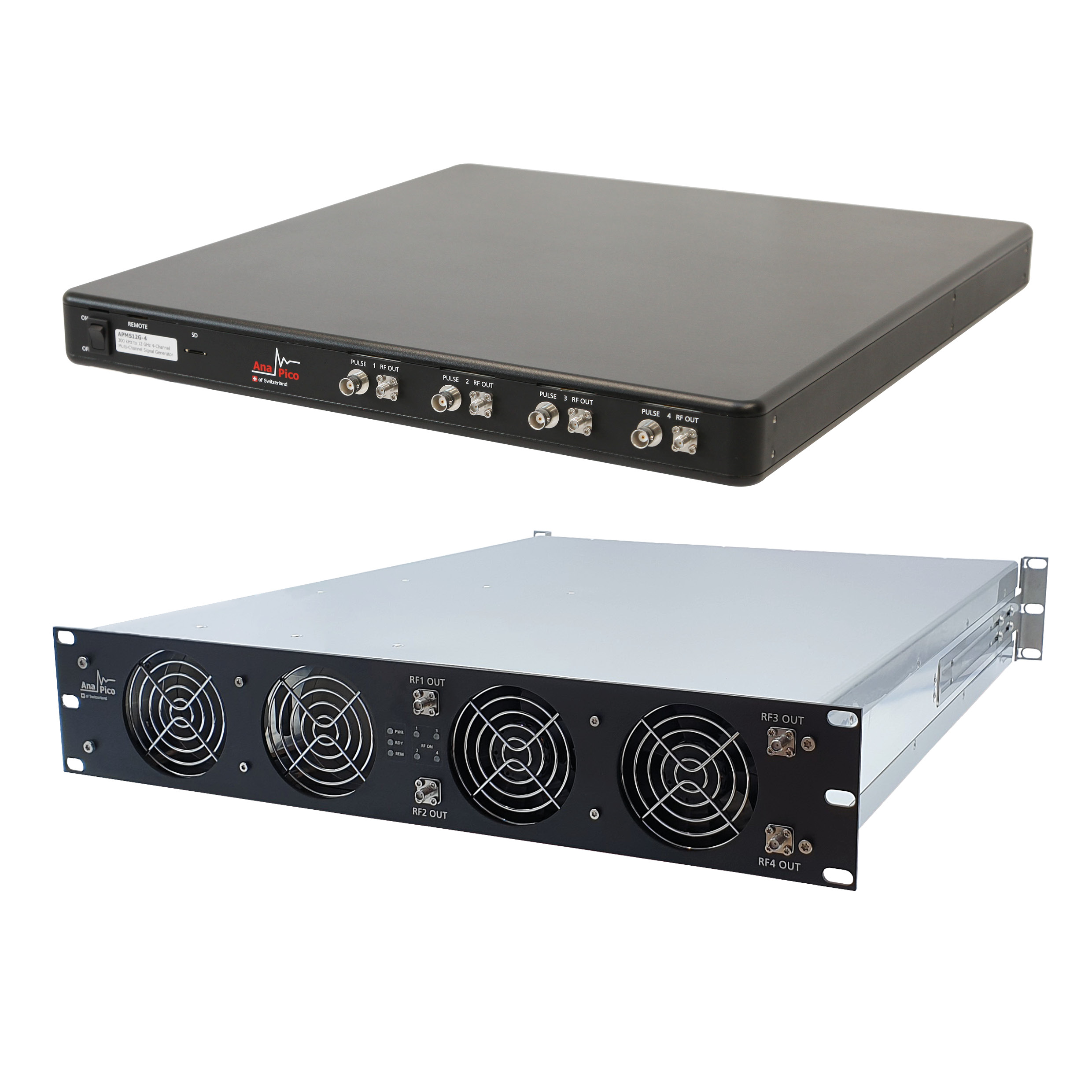
Multi-channel Signal Sources
Electronically generated signal frequencies always have phase noise or frequency jitter. Over time and with varying ambient temperature, the signals will drift further. Generating accurate and stable signal frequencies and, for many applications, maintaining the relative frequency and phase stability among multiple channels are a fundamental and ongoing challenge. If the phase difference between two signals at the same frequency remains constant—in reality, the phase difference variation remains small over time—the two signals are considered phase coherent. Multi-channel phase-coherent signals are widely used in applications such as quantum computing, radar, beamforming for “smart” antennas and spectroscopy. To support these various applications, AnaPico has developed a portfolio of phase-coherent signal sources.
ANALOG AND VECTOR MODELS
The APSYN420-X, APUASYN20-X and APSYN140-X multi-channel, phase-coherent frequency synthesizers have upper frequency options of 20, 20 and 43.5 GHz, respectively, with phase noise of -100 to -115 dBc/Hz at 10 kHz offset from a 20 GHz carrier. The maximum output power from these units is up to 25 dBm, and they work with reference input frequencies of 10, 100 and 1 to 250 MHz, respectively, providing reference outputs of 10 and 100 MHz.
The APMS-X series are analog signal generators with multiple, phase-coherent outputs and frequency options of 6, 12, 20, 33 and 40 GHz and a phase noise of -115 dBc/Hz at 10 kHz offset from a 20 GHz carrier. The signal generators provide amplitude, frequency, phase and chirp modulation and output power levels from -90 to +25 dBm, depending on the configuration. Reference input frequency options with the APMS-X series are 10, 100, 1000, 3000 and 1 to 250 MHz, with reference outputs at 10 and 100 MHz and 3 GHz.
The APVSG-X series are multi-channel, phase-coherent vector signal generators (VSGs) with upper frequency options of 6, 12, 20 and 40 GHz and phase noise of -95 dBc/Hz at 10 kHz offset from a 20 GHz carrier. The series provides output levels from -60 to +15 dBm at 20 GHz, and the output can be modulated with analog amplitude, frequency and phase modulation and I/Q digital modulation with a 400 MHz bandwidth. Reference input options are 10, 100, 1000, 3000 and 1 to 250 MHz, and the VSGs provide reference outputs at 10 and 100 MHz and 3 GHz. The APVSG-X series has a fast control port for fast digital I/Q streaming, fast settling frequency hopping and fast address-driven I/Q playback.
All the signal sources in AnaPico’s portfolio have common characteristics: phase coherence of ±0.2 to ±0.5-degree RMS phase variation at 5 GHz over 5 hours, with inter-module synchronization through a high frequency clock. After calibration, the frequency accuracy is ±10 ppb at room temperature, with drift of ±0.5 to ±5 ppb per day, optionally selectable. The units have low-power consumption, about 20 W per channel, and were designed to be compact. Four independent channels fit in a 1U 19-in. rack-mount module.
PHASE COHERENCE
Based on years of microwave circuit design experience, AnaPico uses several approaches to achieve excellent multi-channel phase coherence. All output channels are digitally synthesized from a common, high frequency, phase-locked loop (PLL)-based reference; the PLL’s controlled lock-in phase has very low phase noise. All the digital frequency synthesis channels use components selected for minimal additive noise, and all channels are packaged in a similar thermal environment to ensure same direction temperature changes and similar long-term drift. To achieve phase coherence between channels in different physical modules with independent frequency references, a 3 GHz synchronization signal is used, provided in addition to the references at 10, 100 and 1000 MHz.
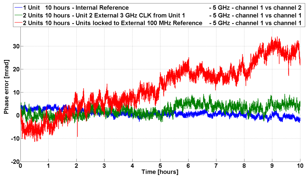
Figure 1: Measured phase coherence between channels vs. time.
Figure 1 shows the phase coherence performance of the APMS-X series. The blue curve represents the measured phase difference between two channels at 5 GHz. The two channels are in the same rack-mountable module set in a normal laboratory environment and measured over 10 hours. The phase difference varies across a small range: ±0.2 degrees RMS over 5 hours. The green curve shows the phase difference between two channels from two different rack-mountable modules and using the 3 GHz synchronization signal. All other conditions are the same as for the blue curve. Here, the phase difference variation is around ±0.5 degrees over 5 hours. The red curve repeats the measurement shown by the green curve, except a 100 MHz external reference for the inter-module synchronization signal is used rather than the 3 GHz reference. The larger phase error shows the benefit of using a higher reference frequency to achieve better phase stability.
PHASE-COHERENT SWITCHING AND MEMORY
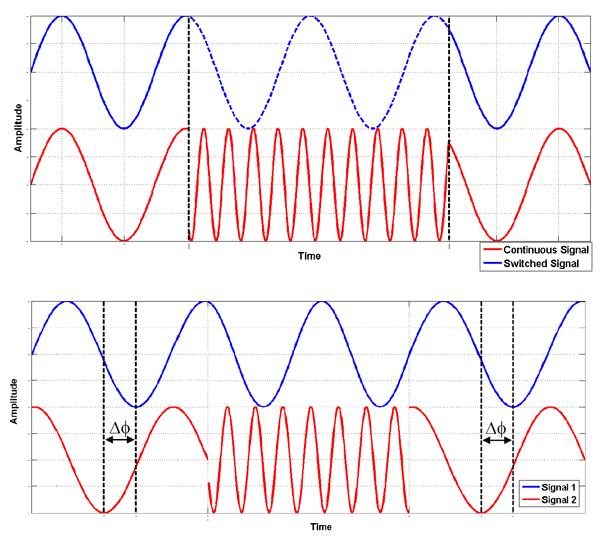
Figure 2: Phase-coherent switching (a) with phase memory (b) option.
The APMS-X and APSYN140-X series offer phase-coherent switching (option PHS), illustrated in Figure 2. Once two channels are set to the same frequency, they will always have a deterministic relative phase position, i.e., the phase difference remains the same over time. When one of the channels changes frequency, it maintains the constant phase difference once both channels are again at the same frequency. Only the channel which changed frequency exhibits a phase discontinuity (see Figure 2a).
Option PHS also offers a feature called phase memory. Consider a single channel where the frequency hops. When the frequency hops back to the previous frequency, the phase returns to the prior state, as if the frequency never changed (see Figure 2b). For multi-channel sources, the phase memory feature quickly restores the “saved” phase difference after switching signal sources off and on.
Combining the phase-coherent switching and phase memory with the fast frequency settling characteristic of the signal sources enables the signal sources to configure a frequency hopping system that can be used to steer an antenna array with phase differences corresponding to sustained beam directions.
SUMMARY
AnaPico has developed multiple models of multi-channel and phase-coherent frequency synthesizers and signal generators for various market applications. AnaPico’s microwave circuit design expertise enables phase coherence and phase-coherent switching with best-in-class phase noise performance among all the multi-channel signal sources in the market.
For further information about our product range contact our support team.